Thought Leader Thursday: Four things needed to get Accurate Results with Finite Element Analysis
A well-known saying when talking about computers is “Garbage In leads to Garbage Out”. This is certainly true when performing Finite Element Analysis (FEA). In this post, I will discuss ways to ensure that your FEA results actually mean something.
Use the appropriate element sizeThis is less of an issue these days as preprocessors can generate millions of elements in few minutes and computers have become powerful enough to run these huge models. If the models are meshed too coarsely, the results will be inaccurate. In addition to element size, element shape is also an issue. Poorly shaped elements (especially in areas of high stress) can lead to erroneous results. The same can be said of poorly shaped elements in areas of high stiffness. With the modern preprocessors, it is quite easy to split surface elements into four and solid hexa elements into eight smaller elements. The results should be compared to the original coarser meshed model. If the results vary, then the original mesh was too coarse. In this case, the finer mesh should be used. The mesh should be split again to check that the results have converged to the accurate result.
Get the right number of Rigid Body ModesThe most important sanity check when looking at a new model is to run a free-free eigenvalue analysis. You should get the correct number of rigid body modes (typically six). If you have too few, then the model is being constrained by malformed Multi-Point Constraints (MPC), spring elements (CELAS) that are directional, but not aligned to the specified axis, or the incorrect use of Rigid Elements. Modern FEA codes have diagnostics, such as GROUNDCHECK, that can point out to the modelling error that is constraining out the Rigid Body Modes. Another approach to locate the error is to output the element strain energy and look at the results in a post processor. The “hot spots” will point you to the problem.
Another issue is having too many Rigid Body Modes. This is caused by mechanisms in the model. To find the mechanisms, look at the displacement results of all the Rigid Body Modes in a post processor. This will show where the issue is.
Finally, it is important that the Rigid Body Modes are truly rigid. The frequency of these modes should be less than 0.05. If you have rigid body modes in frequencies greater than this (especially if they are above 0.2), then there is some modeling error that causes these modes to act like structural modes. As with not enough rigid body modes, use diagnostics such GROUNDCHECK in OptiStruct®, and/or view the element strain energy distribution in the post processor.
Have a Numerically Well Conditioned ProblemHaving elements that are too soft or to stiff leads to problems of numerical ill conditioning. The analysis results could be off by an order of magnitude or more. The most common mistake is to use very stiff springs to connect two rigid elements in order to overcome the problem of double dependency. Double dependency happens when each grid is the dependent grid of a rigid element. The stiffness values should be in the range 1.0E6 to 1.0E12. In many models we see values of 1.0E15 or even 1.0E19. These large values reduce many digits of accuracy in the analysis results. The high values can be reduced automatically for all elements in the model in OptiStruct using PARAM,BUSHSTIF.
Another issue is to have elements that are two soft. This is most commonly caused by having very thin bending elements. Coating the surface of solid elements with 2D elements is a common practice to get the stress values on the surface of the solids. Since the bending stiffness of plate is proportional to t^3/12, an element with a thickness of 0.001 will have a bending stiffness in the range of 1.0E-10. This can lead to singular or near singular matrices. If these singularities are not constrained automatically by the FEA program, they can lead to analysis inaccuracies and long run times. This is especially true in eigenvalue analysis (performed with Lanczos or by the Multi-Level Substructuring Method). The key is to make these thin elements membrane only by removing the bending properties and/or materials. This can be done automatically in OptiStruct using PARAM,SHL2MEM.
Fluid-Structure Coupling
In Noise, Vibration, and Harshness (NVH) Analysis, the air mesh is usually not aligned perfectly with the surrounding structural mesh. A search algorithm is used to determine which structural grids are influenced by the outer face of each fluid element. In many cases, not all the outer fluid faces are connected to structural grids. This is shown by the blue elements in the figure below.
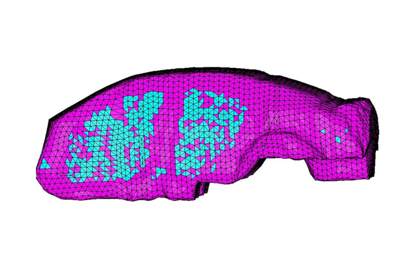 These faces are “acoustically rigid”, which means that the sound is reflected back into the air and does not interact with the structure. In most FEA programs, you can run a check run in order to get a file that can be viewed in the post processor to make sure that every fluid face is coupled. For example, you can load the automatically generated by OptiStruct filename.interface file into HyperMesh® to generate a picture similar to the one above. It is especially important to do this repeatedly as many times the structural mesh is modified while the fluid mesh is not. I have seen very few couplings that were correct without having to adjust search parameters or even having to remesh the fluid domain.
I have discussed some important considerations that should be addressed to get accurate FEA results. These are element size and quality, checking for the correct number of rigid body modes, having a numerically well-conditioned problem, and checking for good fluid-structure coupling in NVH analysis. Following these simple guidelines will help the analyst get good results and not spend time “debugging” the model when the results seem inaccurate. One final hint: Always read through your output file for any warnings that were detected by the analysis code. These could point out to other potential modelling errors.