Motorsport to Automotive – Electric Powertrains
It is widely known that one of the biggest focal points of Automotive OEM Research and development in recent years has been electric vehicles. It represents quite a challenge because while OEM manufacturers are very skilled at building internal combustion engine (ICE) cars, electric cars are relatively new territory. Fortunately, simulation software, such as the ChassisSim Electric powertrain module that has been used in Formula E, offers a very effective and easy solution.
When designing an electric powertrain, it is important to understand a multitude of variables including; the voltage and current draw, battery capacity, and engine and regen characteristics. To analyze the data, you need to know, pack voltage and temperature, charge power, voltage current, and pack usage. An example of this is shown below in Figure 1.
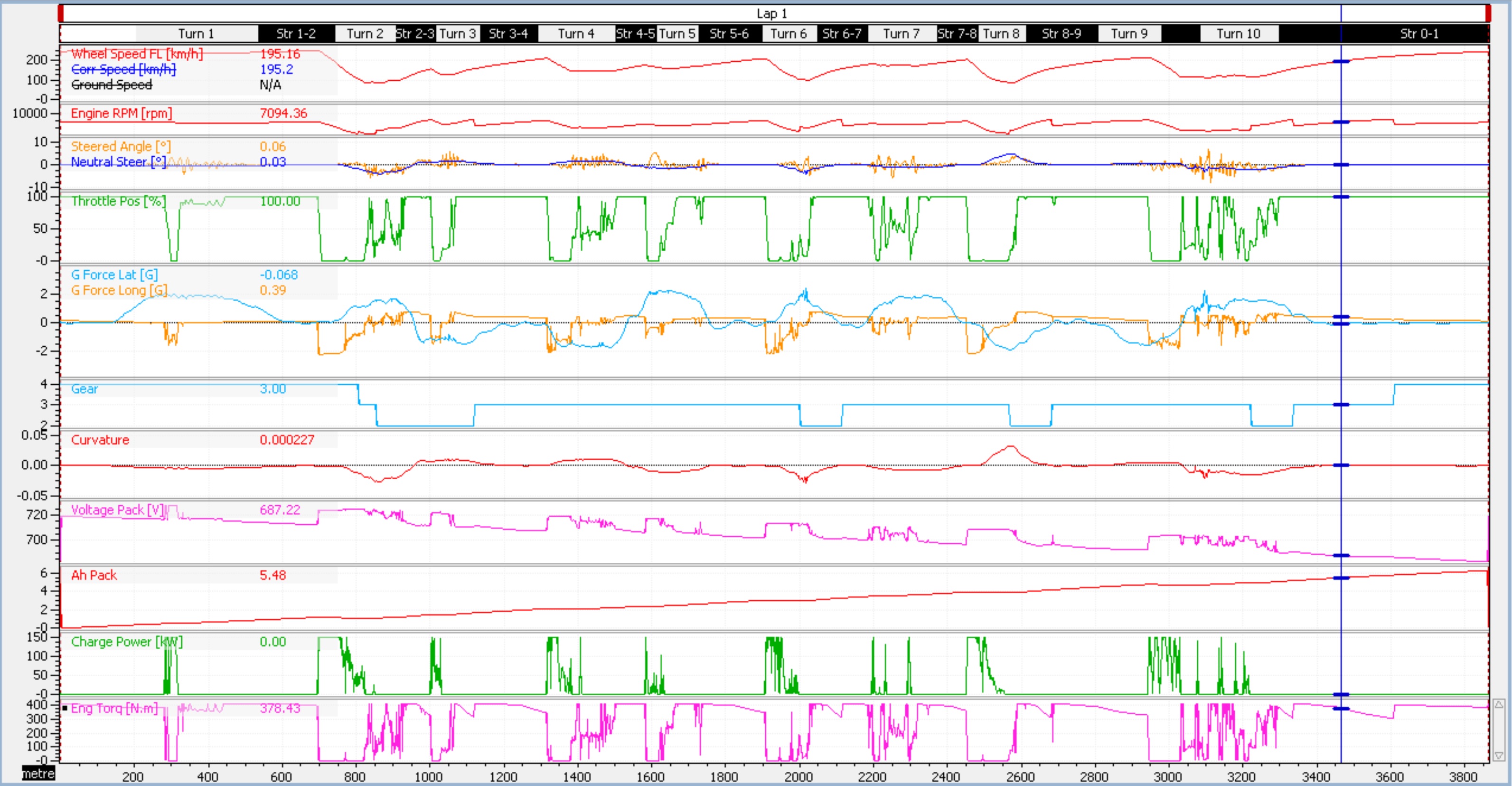 Figure 1 – Example of the output of the electric powertrain.
The variables of interest are; the four last points of the trace that shows pack voltage, pack usage (Ah), charge power that indicates what the pack is being charged at and lastly, the engine torque.
Setting up an electric powertrain is not as difficult as one might think. I can’t speak for other simulation packages but with ChassisSim, it’s just a matter of clicking on the electric powertrain tab and filling in the details. A sample of the dialogs required is shown in Figure 2.
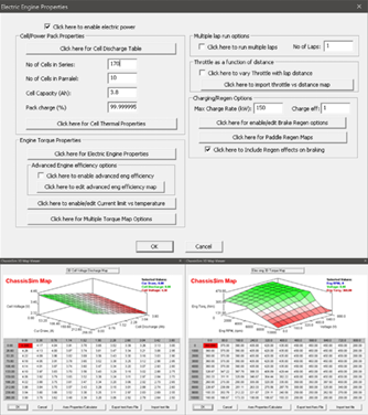 Figure 2 – Dialogs required to get the electric powertrain up and running.
Believe it or not, everything that you have seen outlined in Figure 2 is all that you need to get started with a basic electric powertrain module. This will enable you to calculate pack voltage, the pack’s usage or Ah, and charge power chrematistics. In ChassisSim, this is already combined within an existing vehicle dynamics package so you can start to see the trades offs in pack weight and the impact that will have on vehicle performance.
But how can we adapt this motorsport package to use for an OEM application? The answer is actually very straightforward.
The first thing you need to do is to define a curvature file that represents typical road use. This is a plot of inverse corner radius vs. distance. This can be done in a number of ways. The first method is to log a typical car with lateral g and speed. All you need to do is then export the data at 10 Hz and filter the lateral accelerometer signal which will provide you with the basis of the curvature vs. distance file. Another way is to generate an xyz plot of a trajectory from Google Earth or equivalent and reverse engineer the curvature file needed.
Next, define a distance vs. throttle application curve. This plots throttle application as a function of distance which is shown graphically in Figure 3.
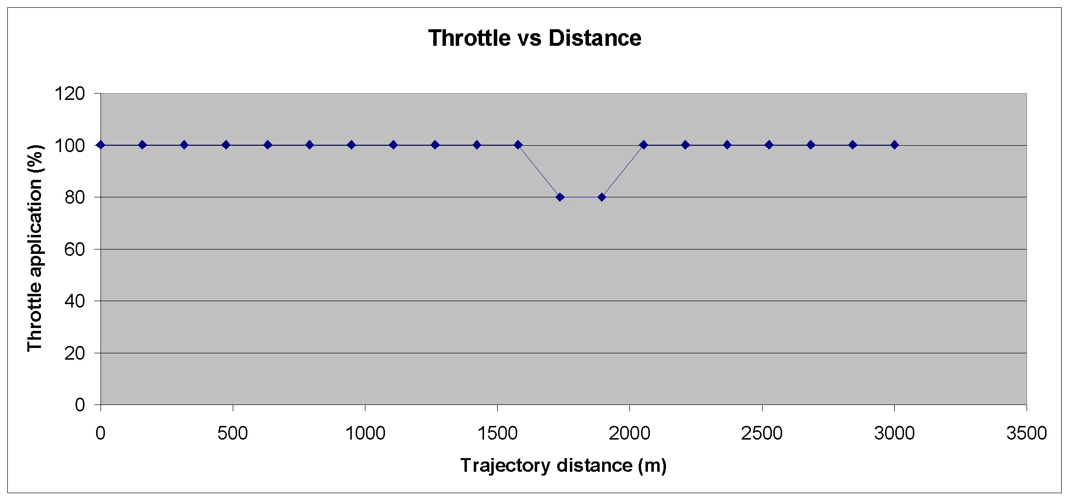 Figure 3 – Plot of throttle application vs distance.
The way that this has been setup only requires for you to define the sections that you need to apply minimum throttle to; the rest you leave at 100%. The file has a maximum size of 100 points. Because it uses linear interpolation, if for example, between 2000m to 4000m of your trajectory you use 20% throttle, you just define that in the text file.
The last step is to define the braking requirements. The purpose of this requirement is that electric car batteries charge using the energy harvested from the brakes. For a racing application, you assume maximum braking application. This is an essential requirement for motorsport use. However, OEM applications require a bit more finesse. Fortunately, there are a number of ways this can be accomplished. The first, is to modify the maximum possible braking used. While this is just a rough analysis, it is perfectly fit for the purpose. The second, much more refined way of doing this is to define distance bounds where the maximum deceleration can be specified.
Once all of these elements are in place, you can quickly define what is needed from the battery pack and how it will impact vehicle performance. As shown in Figure 1, ChassisSim will return all of the key elements you need to know when putting together an electric powertrain. What we have just discussed in terms of putting together a curvature file as well as defining a throttle and brake map for motorsport applications can be readily adapted for road car use. This ensures that you have reliable numbers.
In closing, simulation software is essential for determining the needs of an electric powertrain. The ChassisSim Electric powertrain module, race proven in Formula E, can be readily adapted for road car use. Furthermore, since this is already part of a comprehensive multi body vehicle dynamics package in addition to tailoring what you need from an electric powertrain you can quickly evaluate its impact on other aspects of vehicle performance. Don’t just take our word for it, download ChassisSim from the Altair Partner Alliance program and evaluate it for yourself.
This guest contribution on Innovation Intelligence is written by Danny Nowlan, Director of ChassisSim Technologies. ChassisSim is a multibody vehicle dynamics software that allows race teams and vehicle dynamics engineers to simulate all aspects of vehicle behavior well before the car turns its wheels. ChassisSim is available through the Altair Partner Alliance.
When designing an electric powertrain, it is important to understand a multitude of variables including; the voltage and current draw, battery capacity, and engine and regen characteristics. To analyze the data, you need to know, pack voltage and temperature, charge power, voltage current, and pack usage. An example of this is shown below in Figure 1.
Figure 1 – Example of the output of the electric powertrain.The variables of interest are; the four last points of the trace that shows pack voltage, pack usage (Ah), charge power that indicates what the pack is being charged at and lastly, the engine torque.
Setting up an electric powertrain is not as difficult as one might think. I can’t speak for other simulation packages but with ChassisSim, it’s just a matter of clicking on the electric powertrain tab and filling in the details. A sample of the dialogs required is shown in Figure 2.
Figure 2 – Dialogs required to get the electric powertrain up and running.Believe it or not, everything that you have seen outlined in Figure 2 is all that you need to get started with a basic electric powertrain module. This will enable you to calculate pack voltage, the pack’s usage or Ah, and charge power chrematistics. In ChassisSim, this is already combined within an existing vehicle dynamics package so you can start to see the trades offs in pack weight and the impact that will have on vehicle performance.
But how can we adapt this motorsport package to use for an OEM application? The answer is actually very straightforward.
The first thing you need to do is to define a curvature file that represents typical road use. This is a plot of inverse corner radius vs. distance. This can be done in a number of ways. The first method is to log a typical car with lateral g and speed. All you need to do is then export the data at 10 Hz and filter the lateral accelerometer signal which will provide you with the basis of the curvature vs. distance file. Another way is to generate an xyz plot of a trajectory from Google Earth or equivalent and reverse engineer the curvature file needed.
Next, define a distance vs. throttle application curve. This plots throttle application as a function of distance which is shown graphically in Figure 3.
Figure 3 – Plot of throttle application vs distance.The way that this has been setup only requires for you to define the sections that you need to apply minimum throttle to; the rest you leave at 100%. The file has a maximum size of 100 points. Because it uses linear interpolation, if for example, between 2000m to 4000m of your trajectory you use 20% throttle, you just define that in the text file.
The last step is to define the braking requirements. The purpose of this requirement is that electric car batteries charge using the energy harvested from the brakes. For a racing application, you assume maximum braking application. This is an essential requirement for motorsport use. However, OEM applications require a bit more finesse. Fortunately, there are a number of ways this can be accomplished. The first, is to modify the maximum possible braking used. While this is just a rough analysis, it is perfectly fit for the purpose. The second, much more refined way of doing this is to define distance bounds where the maximum deceleration can be specified.
Once all of these elements are in place, you can quickly define what is needed from the battery pack and how it will impact vehicle performance. As shown in Figure 1, ChassisSim will return all of the key elements you need to know when putting together an electric powertrain. What we have just discussed in terms of putting together a curvature file as well as defining a throttle and brake map for motorsport applications can be readily adapted for road car use. This ensures that you have reliable numbers.
In closing, simulation software is essential for determining the needs of an electric powertrain. The ChassisSim Electric powertrain module, race proven in Formula E, can be readily adapted for road car use. Furthermore, since this is already part of a comprehensive multi body vehicle dynamics package in addition to tailoring what you need from an electric powertrain you can quickly evaluate its impact on other aspects of vehicle performance. Don’t just take our word for it, download ChassisSim from the Altair Partner Alliance program and evaluate it for yourself.
This guest contribution on Innovation Intelligence is written by Danny Nowlan, Director of ChassisSim Technologies. ChassisSim is a multibody vehicle dynamics software that allows race teams and vehicle dynamics engineers to simulate all aspects of vehicle behavior well before the car turns its wheels. ChassisSim is available through the Altair Partner Alliance.