How to Handle Long Time Signals with Nonlinear Structure Efficiently
Typically, there are two ways of considering variation of load over time in a finite element-based fatigue analysis:
- The road load data is integrated in the finite element (FE) analysis directly. The results in the form of transient stress responses serve as direct input for the subsequent fatigue analysis in a transient method 1).
- The FE analysis uses a unit load case-based approach. The stresses are determined according to normalized static unit loads, the corresponding road load data are initially disregarded. The combination of stress results and the road load data takes place in each direction (usually called channels in test labs) applying the principle of linear superposition 2).
The first approach does not use the linear superposition principle. Nonlinearities such as contact and large deformations can therefore be used in the FE analysis and the subsequent fatigue analysis.
Disadvantages of this FE analyses are above all to be found in the considerably high numerical effort, the larger amounts of data as well as in the fact that in the non-linear case every road load data causes a new calculation run. For these reasons, this procedure is usually limited to short & simple load profiles for reasons of efficiency in practice.
The second option avoids all these disadvantages of the FE analysis and offers the advantage on the side of the fatigue analysis that general, random, and almost arbitrarily long load-time profiles can be processed. Another significant advantage is that the FE results – once calculated for the unit load cases – can be combined with various time-history data in the fatigue analysis for the different maneuvers and road profiles.
These advantages are bought by any compromises in accuracy due to the neglect of possible non-linearities.
We present an analysis procedure, that bridges the gap between the two approaches, that allows the use of non-linear FE calculation results without having to sacrifice the efficiency of this second analysis procedure using superimposed (interpolated) discrete stress result.
The core idea lies in an interpolation method, in which the FE analysis does not follow the original load path but calculates neighboring points first.
These neighboring points result by placing a grid around the load curve. This results in a rectangular grid in the case of two forces and a cubic 3D grid for three forces. Non-linear FE analyses are carried out for these discrete grid points. The deformation and stress states are interpolated from the results at the corner points for all times. Grid points that are not required for interpolation - because the load curve is not passing by - don't need to be calculated. This means that unnecessary states in the FE analysis and therefore channels in the subsequent fatigue analysis can be skipped.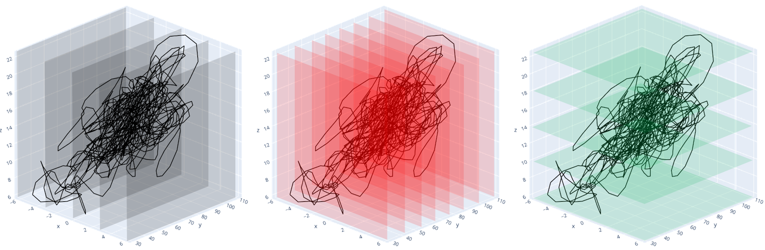
The advantage of a software to handle the solver decks for such FEA in the discrete loading point and the factors needed for the interpolation of stress and displacements coming close to these discrete points is obviously seen 3). The displacements are also processed because in combination with stress results or fatigue results, it is particularly helpful as the deformations, superposed stresses, and damage can be animated in nearly no time.
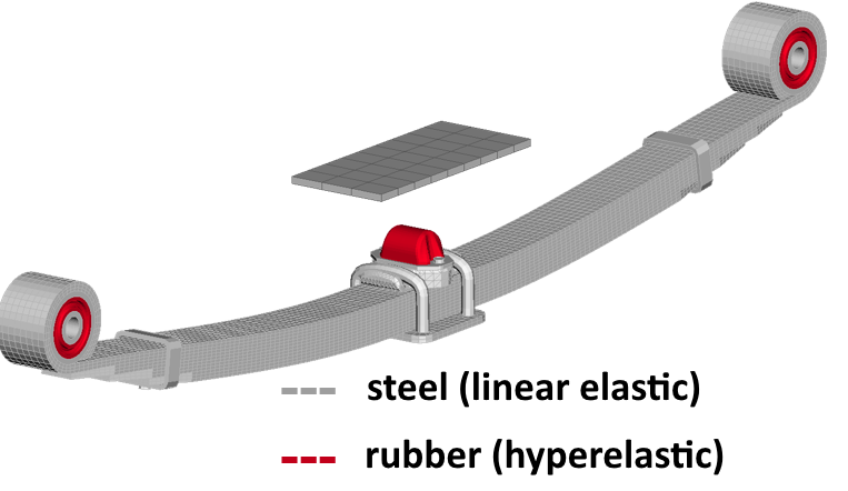
The application of a leaf spring is intended to illustrate the process. As a special feature, a few non-linearities are included in this example (contact, hyper-elastic material behavior, and large deformations).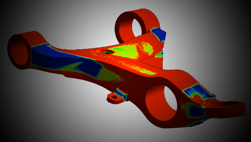
The external load in the form of displacements in the x, y and z directions are applied at the point of excitation (see figure below).
The load curve is discretized with five steps in the x-, eight in the y- and five in the z-direction (see figure 1).
This results in a total of 5x5=25 FE analyses with 8 steps (y-direction) each. So theoretically 200 results fill the grid.
In our example we apply a software tool, that has been developed specially for the use with our fatigue software FEMFAT. The tool is called ELASTOLOADS and the module to combine and superimpose the stresses for fatigue analysis is FEMFAT channelMAX. Elastoloads has an automatic filtering feature, which reduced the necessary number of results from 200 to just 107 channels relevant for the given load histories, respectively the above ready combined load curve.
The results show damage distributions, equivalent stress histories and the accumulated damage over time at selected points of the structure 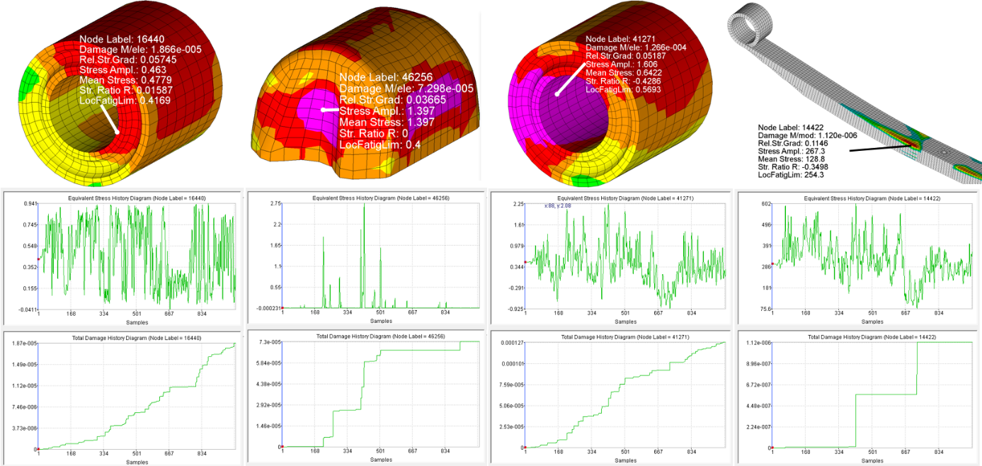
Summary
With this procedure it is possible to evaluate non-linear phenomena in combination with any length of road load data very efficiently. There is a tool available for the combination with the fatigue analysis in FEMFAT channelMAX, called ELASTOLOADS. Due to the high degree of automation, this tool can be excellently included in the global simulation process.
A good selection of the level of discretization leads to a reduction in the required FE analyzes and a minimization of channels in the fatigue analysis while keeping the accuracy still high.
The additional animation of the results simplifies the evaluation and enables even deeper insight into the underlying deformation and damage mechanisms.
1) The transient method in FEMFAT is part of FEMFAT max and is called TransMAX.
2) The fatigue analysis method of channel based superimposed data in FEMFAT max is called ChannelMAX.
3) APA Partner MAGNA has developed the tool ELASTOLOADS because fatigue of elastic materials like rubber have been the first application for it. If you are interested in ELASTOLOADS and using FEMFAT via APA, please contact [email protected] or [email protected].