A Design-Validation-Production Workflow for Aerospace Additive Manufacturing
Megan Lobdell, Brian Croop, and Hubert Lobo; DatapointLabs Technical Center for Materials Sridhar Ravikoti and Robert Yancey; Altair Engineering Inc.
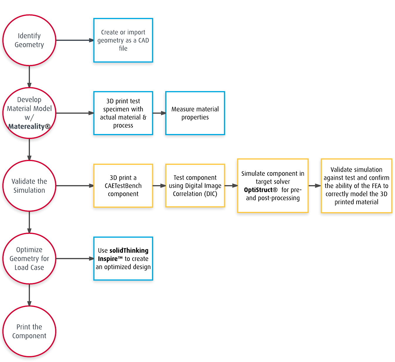
The aerospace industry is implementing 3D printing on a selective basis, particularly for one-off and small-lot production, and also to produce parts that cannot be made using conventional manufacturing processes. With 3D printing, there is this incredible possibility to build a solid model, optimize its shape using topology optimization, and then directly print it to make a ready-to-use part. A critical step is to ensure that the part will perform as simulated. This is because simulation includes uncertainty from the assumptions of the model. This uncertainty is often left untested until the prototyping stage. A mid-stage, CAETestbench™ validation is added to the design workflow to measure the simulation accuracy before parts are made, bringing confidence to the engineer’s model.
With the advent of 3D printing and additive manufacturing, manufacturing designs previously thought difficult to produce can now be generated quickly, efficiently and without tooling. In the aerospace industry, weight is of great importance to the engineering design. In modern light-weighting strategies that involve geometric optimization, the goal is to generate designs that meet the original performance requirements, but with less material. While in the past, overdesign would be acceptable as a means to prevent part failure, a key requirement of the new scenario is to ensure that the optimized part does not fail. For this strategy to succeed, it is necessary that the simulation be accurate up to failure.
Traditionally, the design process involves much iteration between the designer and the analyst, where the designer submits a design to the analyst, who completes their analysis and sends recommendations back to the designer. The process is then repeated until a valid design meets the analysis criteria. The design is then handed to the manufacturing team, which then may have additional constraints or concerns, and iterations can continue. Additive manufacturing coupled with topology optimization allows the design-and-analysis and manufacturing iterations to be reduced significantly, or even eliminated. To ensure that the part will perform as simulated, a mid-stage validation is conducted on a standardized part before creating the final products. This is because it is often difficult or even impossible to accurately test and replicate the real life boundary conditions of the product with adequate fidelity for quantitative comparison.
This Workflow may help to reduce the time required to design, analyze, and produce an aircraft component, while also significantly reducing its weight. The workflow was put to the test with a 172 Cessna rear elevator bellcrank. The goal was to optimize the part for weight based off the maximum allowable load input, while ensuring the part has a Factor of Safety of 2 and a maximum deflection of 3.8mm.
Density and stress-strain curves were measured and the resulting data were uploaded to Matereality. Elastic and elastic-plastic piecewise material models were created using Matereality’s CAE Modeler software. CAE Modeler gives the user graphical control to specify the stress-strain points used in the model and also calculate modulus and ultimate strength for the material model. The material files were stored in the users’ Workgroup Material DatabasePro ready for export to HyperMesh® through the Matereality-HyperWorks connectivity.
Prior to the optimization, a mid-stage validation of the simulation was performed on a 3D printed Cornell bike crank, which has features designed to probe the quality of the simulation. Through the use of digital image correlation (DIC), images of the strain field on the face of the bike crank were gathered to compare to the simulated strains to evaluate fidelity of the simulation to the test. The elastic response validation was set up in HyperMesh with a solid map mesh, then simulated using the OptiStruct® solver. Failure validation was also set up in HyperMesh using a refined mesh, then run with the nonlinear explicit analysis solver, RADIOSS®. A picture of the broken crank and the simulation image were compared. Not only did they break in the same locations, but the simulation calculated a similar failure load compared to the physical test.
With a measure of confidence in the simulation now established, an optimization of the part was done using the solidThinking Inspire™ structural optimization software. The resulting conceptual design achieved a mass reduction of 45%, which was significant for any structure and especially for aerospace structures, where minimizing weight is critical.
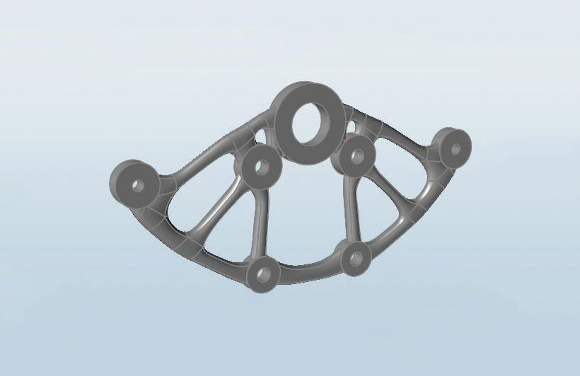 Smooth Result Interpretation using polyNURBS technology
For more details about this workflow, click here to read the full whitepaper.